Written by Gianluca Mando, Head of Products Design Authority, at Thales
Today, the process of digitizing transport systems is underway and the definition of the autonomous vehicle concept is part of this trend. However, given its internal complexity, it may sometimes not be immediately clear even to the most experienced of designers what are the main functional and technical elements that compose it. This technical news gives an architectural vision of how an autonomous tram will work in a near future, when urban mobility paradigms will be considerably influenced by self-driving cars and other autonomous vehicles.
Here we want give an architectural vision of the autonomous tram as it has been conceived by Thales Italia in ELASTIC, where it has developed two important functions: the advanced autonomous localization system NGAP localization (Next Generation Autonomous Positioning) and the obstacle detection and avoidance functionality ADAS (Advanced Driver Assistance System). When a designer starts to describe a complex system as an autonomous tram, there are several options as the system can be viewed from different perspectives: in terms of physical components, development stages, logical functions or process steps. We consider two architectural viewpoints: 1) a technical, which is related to hardware and software components and their implementations, and 2) a functional, which includes the description of processing stages that a self-driving tram must have as logical blocks of the whole system.
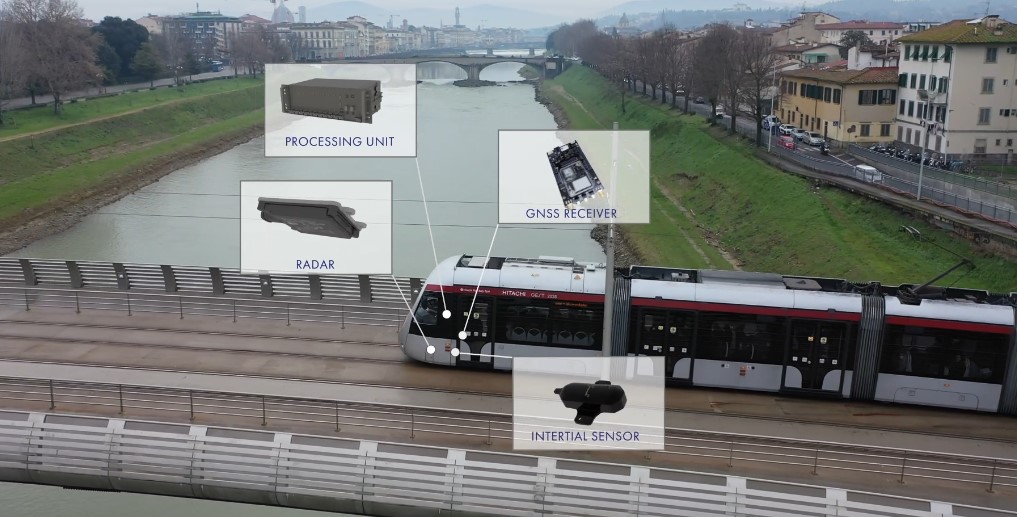
Figure 1: NGAP sensors
Technical View
Hardware and software are the two main layers of the technical view of an autonomous tram architecture and each layer includes components that represent different aspects of the whole system. Some of these components can be seen as an isolated group, but there are some components that act like a backbone within their own layer providing a structure and guidelines for the interactions between all the components. This description is depicted in Figure 2.
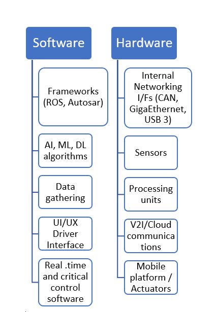
Figure 2: Technical Architecture of an Autonomous Tram system
Future self-driving trams could be referred to as a high-performance computing (HPC) system on tracks because of the complexity in the hardware and software frameworks. They are large complex systems equipped with several sensors, for internal and external monitoring and generating massive amounts of data per journey. In order to handle all this information, communications and processing units are no longer limited to a set electronic control units but instead highly-parallel and heterogeneous edge devices are used to elaborate sensors data, featuring multi-core computing platforms with Graphical Processing Units (GPUs) and Field Programmable Gate Arrays (FPGAs) acceleration devices. In addition to the data generated by the vehicle, in ELASTIC external data is also available from the cloud vehiculated by train-to-ground Vehicle-to-Infrastructure communications (V2I). The tram vehicle itself is part of the hardware view: this is the mobile platform and actuators.
The internal networking interfaces allow each subsystem to exchange information with each other, for example high bandwidth interfaces like USB 3.x, Gigabit Ethernet for sensor data transport, or CAN networks for low bandwidth communication are used in the prototypes installed on-board the trams in Florence.
The software side is also currently evolving, with a strong transition from embedded software running on top of Real-Time Operating Systems (RTOS), to high-level software components including frameworks, libraries and modules that support Artificial Intelligence (AI) methods such as Deep Learning (DL) algorithms required for processing the data. But also, there are software components dealing with different aspects of the vehicle operation, like drivers for data collection from the sensors, user interfacing through the infotainment system, and real-time and critical software for controlling actuators and monitoring the status of the vehicle. Besides, the software frameworks and standards provide a structured way for the software to operate in a concurrent and cooperative way.
One example of software guidelines and frameworks, adopted on the trams in Florence in ELASTIC, is the Robot Operating System (ROS) a well-established software framework providing tools and libraries for autonomy applications.
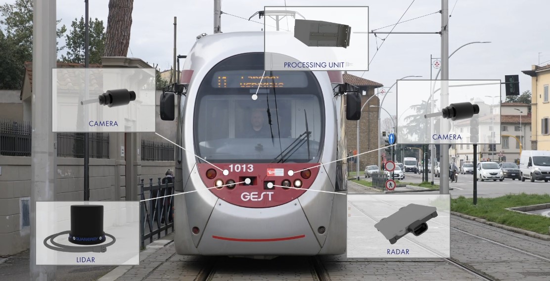
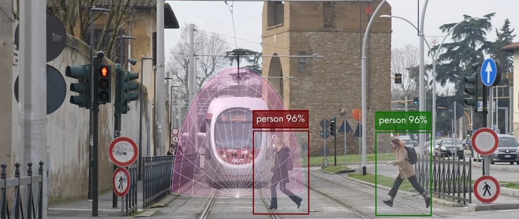
Figure 3: ADAS sensors integrated in the vehicle
Functional View
By analysing an Autonomous Tram from the functional perspective, logical or functional blocks are defined based on the flow of information and the processing stages performed from sensors data to the control of the tram. Considering this, three main functional stages can be identified: perception, planning and decision and motion control. These blocks are represented in Figure 4.
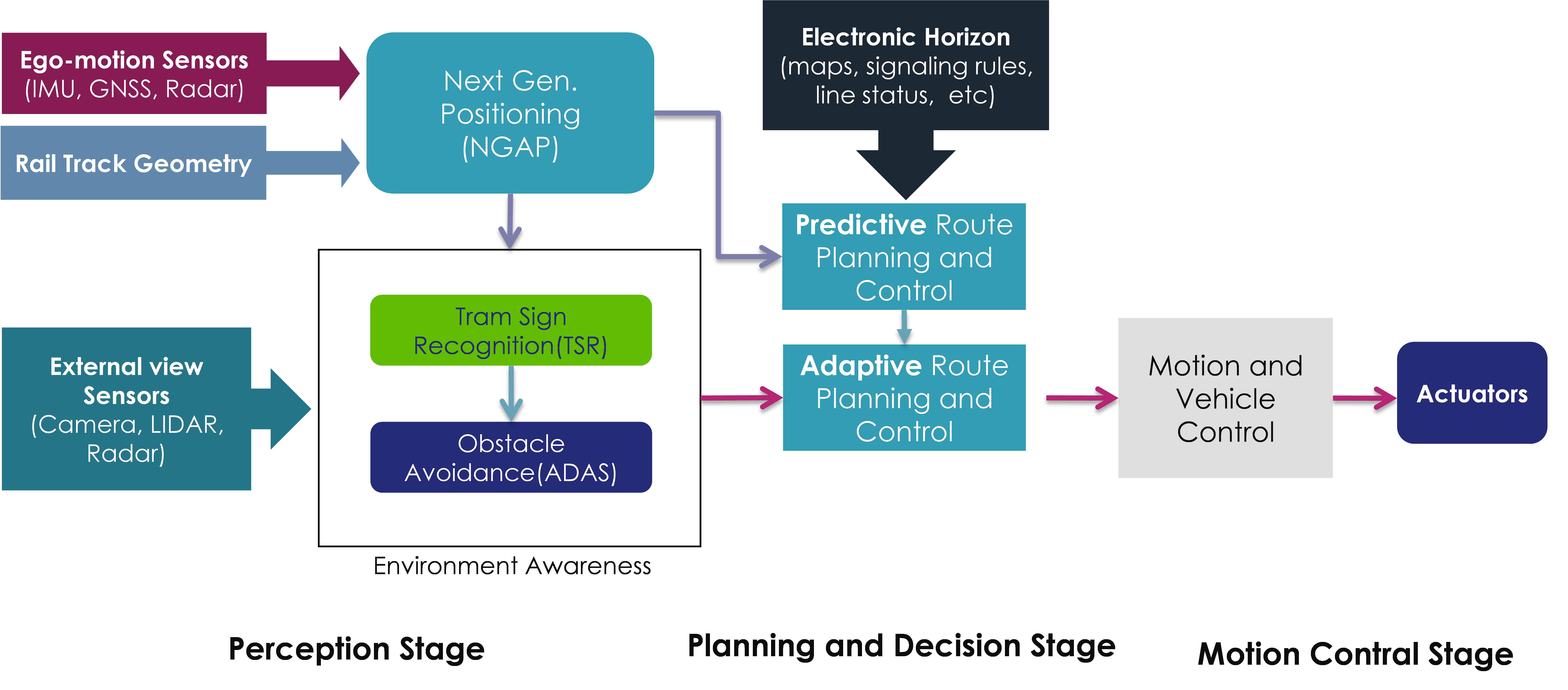
Figure 4: Functional Architecture of an Autonomous Tram system
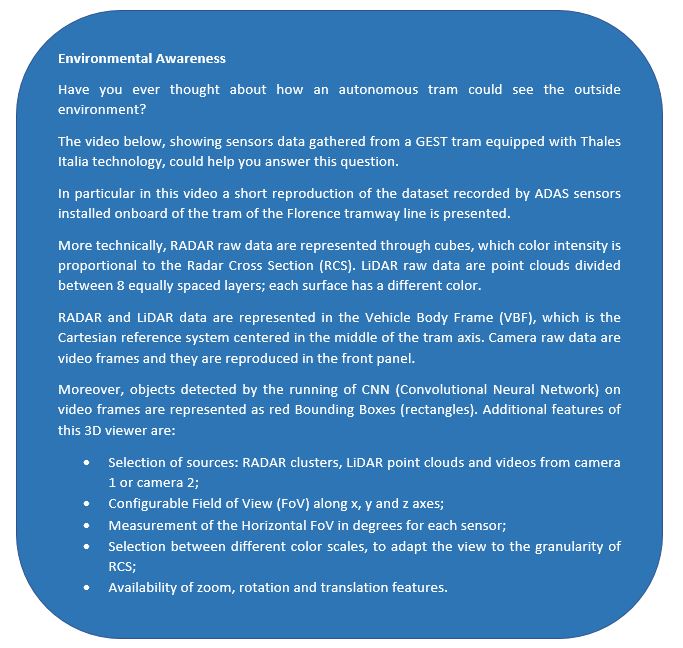
The perception stage is in charge for receiving data from sensors, and create the vehicle status and a world model representation. For performing these two tasks, sensors are categorized into ego-motion sensors that perceive and analyse tram kinematics and are used for sensing the vehicle state, like Global Navigation Satellite Systems (GNSS), Inertial Measurement Units (IMUs), Inertial Navigation Systems (INS), and Tachometers/Odometers. External-view sensors, like cameras, LIDARs, radars and ultrasonic sensors, monitor the environment surrounding the tram to obtain data of the track line and external objects. Localisation NGAP and environment awareness are the main functions performed after collecting all the incoming data from the sensors (see focus on Environment Awareness below). Environment awareness in turn contains two other important functions for the autonomous tram: tram signal aspect recognition and obstacle avoidance (ADAS).
Once the tram and external world status are available for the planning and decision stage, the system can start the navigation plan for the train, like a short-term route from point A to point B approaching a tramway junction area. Adaptive vehicle control is included in this stage to implement the safe operation of the tram.
Furthermore, the predictive vehicle control block supports the planning and decision stage by extending the scope of the adaptive control function by calculating tram’s future dynamics by using data (like maps, signalling rules, provisional speed limits, etc) in the electronic horizon.
The stage of motion control stage manages the way in which the trajectory and control strategy generated in the previous stage is executed on the platform, considering the configuration, track geometry and limitations of it. Again, this stage is highly associated with safety features as it receives high priority commands from the reactive behaviour modules to modify or stop the movement of the tram.
Another key block of this architecture is the functions supervision which is in charge of monitoring all the aspects of the vehicle like the hardware (sensors operation, degraded information, processes performance, energy management, faults management , etc) and the software (autonomy software stack, data values plausibility, etc). The importance of these tasks is that, as a safety-critical system, malfunctioning of hardware or software in a self-driving vehicle, should not result in any harm to people, environment or property. The IEC 50128, 50126 and 50129 are a set of standards for functional safety in railway to address possible hazards arising from faults in electric or electronic devices in a train.
Watch the video below: